You may have seen our bridge concept already. Well, we are happy to report that we have taken the first steps on the road to making that a reality! Here is the plan that we have laid out and a glimpse at what we have done so far.
Our first step in making these bridges was to draw them. Creating digital drawings helps to reduce the workload at almost every other point in the process. It allows for easy modifications, clear communication between the two of us, and ultimately lets us print out our prototypes to get a good feel for them.
Making sure your drawing is printable is the next step; just because your model looks good, doesn’t mean it is printer ready! Computers perceive things differently than a human does, so these problems often aren’t intuitive. For an object to be printed it must be manifold (essentially solid), and every face must be oriented the correct way. All problems, no matter how small or seemingly insignificant, must be diligently found and fixed, or you’ll be in for a surprise when the printing is done! Depending on how precise and thorough you were during the drawing process this can be either fairly painless or a major overhaul.
This three dimensional print is what came from our concept sketches, and actual 3-D test printings. They were printed with a translucent plastic, so unfortunately they are very hard to see. Once we get a coat of paint on them things will be a lot clearer.
We then take that original drawing and use it to make a drawing of the master mold. Our example piece is moderately complex and will require a two part mold to cast the pieces. This requires splitting the original drawing in half along the intended mold part line. Since we were planning for this all along it was originally drawn in two separate pieces that were combined to make the concept sketches and test printings. Each half of the piece is then used to make a master mold with the two halves precisely lined up in the same place in both drawings.
With our end goal in mind, we were also able to build these concepts to work well with the casting process from the satrt. If you design the object to be castable from the beginning it is usually much easier than fixing it later. Starting out knowing what we needed for practical production meant fewer mistakes the first time around!
To these drawing are added all of the necessary features of a master mold: registration keys, air vents, a pour gate, and channels. The registration keys, which keep the mold from shifting, are added to both halves with each side being the mirror opposite of the other. Once the production molds are made from the master molds these keys will interlock and ensure that both sides matchup perfectly together. The air vents, pour gate, and channels are all essential to allowing the resin into the mold and the air out.
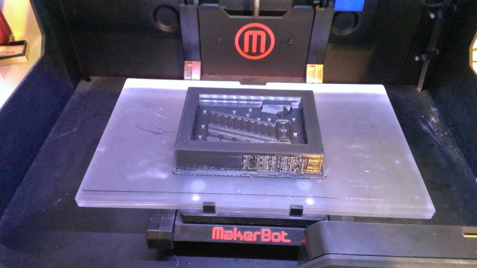
The next step is the printing, which will take over 10 hours for something this size. Lower resolution versions like the ones you see here take much less time, and have their own uses, but the final product needs to be the highest quality. The top surface on this printing has a very pronounced print pattern in it due to the print resolution, and the printer being a little cold. These will tell us if everything will line up how we think it should. For our part two to this article, we will have actual molds and casts to share!


